Practical: Setting up the G33 Suspension Geometry From Scratch
NOTE: Adjusting one setting is likely alter another so always check other settings if moderate to large adjustments are made. Also if you are going to correct the roll centres, do this first, as it will slightly alter the geometry if you do it afterwards.
Step 1: Set the ride height
Firstly corner weights. To get the best traction (if racing) from all four wheels the downward pressure needs to be the same on all for wheels. This would be typically around 230kg per wheel on a G33. Its a common mistake to think that the front of the car is heavier than the rear as the engine is in the front. This is only partly true as the engine is set far back in the chassis, giving a weight distribution of 51% wheels on the front and 49% on the rear. The chassis and body is also heavier on the right hand side, but this is counter acted with the drivers weight. If the corner weights are set the same the nose of the car may be a little high for the best suspension angles, so a compromise has to be reached. For road use simply setting the chassis/body near level should be sufficient.
For basic setting up the car needs to be on a level surface. The heights can be set by winding the lower spring platform up or down on the damper and requires a hex screw to be released in the ring first, and a “c” spanner to turn the ring. On an unmodified car the factory settings are 102-108mm from the centre of the front lower damper bolts to the spring base, and 152-159 mm for the rear. You can make sure the wheel to wheel arch clearance is the same all round (assuming tyre wear is somewhere near even), by simply inserting 2 to 3 fingers in the gap so they all seem the same. Not that precise, but a fair indicator.
Step 2: Setting the Camber Angles
Factory Method
The standard method used by Ginetta is to set the wheel vertical with the lower wishbone level. You are unlikely to be able to do this with the damper and spring in place as the car will lift as you jack the wishbone. Use a bubble gauge on the lower wishbone to get it horizontal and another bubble gauge or plumb line to measure the vertical angle of the wheel. Make any changes undo the top rose joint and rotate it half a turn a time until the desires setting is reached. Use the rim of the wheel for reference, not the tyre. Once done place a glossy magazine under the tyre to reduce any tyre friction and with the full weight of the car back on the wishbone, the wheel should assume a slightly negative camber of around .5 - 1’. This method assumes the ride height to be set at factory values.
Alternatively:
First set the ride heights to the desired level, and get the car on a level surface like a decent level garage floor. Place a glossy magazine under each wheel to act as a low friction point. Place a bubble gauge across the chassis by the wishbone mountings and check its level. If its not, then either the ground is not level or the ride heights are out a bit and need adjusting to compensate. Once the chassis is level, support a bubble gauge vertically next to the centre of the wheel. Measure the distance to the wheel rim at the top and at the bottom from the bubble gauge. The distance between these points needs to be 40mm for the 15” Fondmetal rim. Note the difference in the two readings. The top reading should be greater than the bottom and a bit of school boy trigonometry will give us the following angles:
Distance A - Distance B
| 0mm | 0' |
| 3.5mm | -.5' |
| 7mm | -1' |
| 10.5mm | -1.5' |
The correct setting for road use is between .5’ and 1’ negative camber.
If the settings are out, then jack the car, remove the wheel and undo the rose joint fixing to the upright and lift the top wishbone clear. Loosen the locking nut on the rose joint and rotate it in or out to adjust. Small adjustments make a big difference and it can only be adjusted to a half turn:
One turn of the rose joint is approximately 3mm on the wheel rim.
Once complete reassemble and refit the wheel. Once the wheel is back down on the glossy magazine, bounce the suspension to let the wheel settle to its correct position and recheck.
Step 3: Setting Toe-in Angles
The actual values of toe in can be measured in degrees or mm. In the case of the Ginetta, it's mm, and is measured as the difference in distance between the front and rear of the wheel rim in relation to a centre line down the car's length. A typical value for the front is 2mm per wheel, or a total toe of 4mm between two wheels. In its simplest terms if we put a straight edge along the disk or tyre rim (not the tyre), for every 15” (the rim size) forward of the straight edge will get 2mm nearer the centre line of the car. Unfortunately the Ginetta body does not make a good reference point, so we have to revert to bits of string (I prefer fishing line) and wooden rods to get a reading. The basic idea is to make a perfect rectangle around the car for reference. Firstly get the car on a level surface, jack up each wheel and place a glossy magazine underneath to act as a low resistance pivot. Now lower the wheel and bounce the suspension to settle the springs. Get two wooden rods greater than the car width, and cut two slots in each rod just wider than the rear wheel width. The cut distance has to be the same in each rod. Support the rods at wheel centre height along the front and rear of the car. Tie a cord in each slot in one rod and then extend the cord along side the car into the slots in the second rod and tie a weight (like a socket) to the cord to keep it taut.
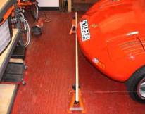
Rails running front and rear to support alignment cords.
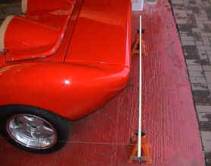
Now the fun bit….. Get the steering straight ahead and measure the distance to the centre of the front wheels from the cord, and adjust the wooden rod at the front until they are the same on both sides. Now repeat this process for the rear wheels. It will take many attempts to get it spot on. You should now have your perfect rectangle around the car for reference. Make sure the wooden rods remain at 90’ to the cords alongside the car. You can now start measuring the distances between the front and rear of the wheel rims to work out the toe in (or out) values using the cord as a point of reference with a ruler. To alter the values, adjust the tie rods on the rear and the track rod ends on the front. You may need to jack the rear of the car to gain access to the bolt securing the tie rod end. The adjustments are pretty crude with half a turn of the rear track rod making about 1mm difference to the toe value. If you do have to jack the car, don’t forget to bounce the suspension after you lower it back down to settle the ride height. The front track rods should be adjusted at .25 of a turn a time on each site to keep the steering central. It's very easy to make over adjustments, and takes considerable time and patience to get right.
Measurement from the cord to the front edge of the rim.
My car from the factory had 5mm rear toe in per wheel (10mm total toe), and consequently ate rear tyres. After the rebuild I started with zero toe in front and rear and at this setting the car was highly unstable. Setting the rear back to 5mm per wheel, gave the familiar black dust that "was" my tyres over the rear bodywork. I slowly reduced this until the dust disappeared, and the car remained stable at speed.
The final toe in values that have worked on my car are 2.5mm (5mm total toe) rear and 2mm (4mm total toe in) for the front. I have personally found this a reasonable compromise between tyre wear and stability. The owner's manual states 2-3 mm for the front and 3-4mm for the rear. The recent values printed in the Ginetta owners magazine by Duncan Campbell are front 2.5 mm +/_ .5mm and the rear 5mm +/- 1mm.
Final Camber Tweaks
Having set up all the static suspension angles the car needs to be road tested and rechecked. The whole aim of the game is to maximise tyre contact to the road for most conditions, and a simple test to see if things are correct is a tyre temperature test. Take the car out for a run over your favourite roads when the road surface is not too hot, and then run your hand over the tyre surface to feel the temperature across the tyre. If it’s hotter on the inside there is too much negative camber, and hotter on the outside not enough negative camber. Tweak the top rose joint half a turn at a time until the temperature is even. I found this to be around .5 degree negative camber. Half a turn on the rose joint makes a big difference. This test assumes the toe in values are correct as this will also affect the temperatures across the tyre as the inside or outside edges scrub the road if the values are to far out.
This has worked on my car for road use, but may not suit everyone.
| Front toe in 2mm per wheel | Front camber -.5' | Front springs 275 lb | Front damper 5 clicks from softest |
| Rear toe in 2.5mm per wheel | Rear camber -.5' | Rear springs - 300lb | Rear damper 5 clicks from softest |
Correction of Bump Steer
Note this is best done without the dampers/springs fitted so the suspension can be moved through its maximum range. If the springs and dampers are left in place, the car is likely to lift before the upper suspension limit is reached.
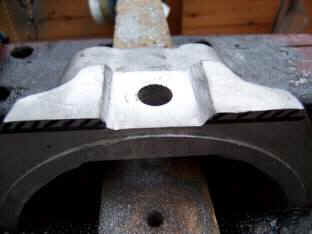
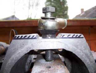
To check if bump steer is present, remove the front glass fibre inner wheel arches and lock the steering. Jack the front of the car high enough to get the front wheels off the ground and support the chassis on axle stands. Now jack the front wheel under lower wishbone and lift the front wheel as high as you can. Now stand above the wheel and look down, and get a colleague to release the jack so the wheel drops. Any bump steer will be seen as the wheel pivots inwards or outwards as it drops. If bump steer is observed, then the height of the track rod rose joint needs adjusting where it pivots on the front upright. The bracket that the rose joint pivots on is much wider than needed, and the extra space is taken up with small spacers. Remove the spacers and replace with washers, and move the rose joint up or down a washer at a time and retry the test until the bump steer is at a minimum. It is not possible to totally overcome bump steer across the whole suspension range, so a compromise has to be reached over the range the suspension is likely to travel in day to day use dependent on the ride height. Ginetta having worked out the required rose joint positions made the small spacers to mach the best settings to make it permanent. One reason such hard springs where used by Ginetta was to limit the suspension travel, and limit the bump steer point.
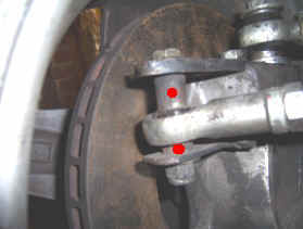
Steel spacers (marked in red) fitted by Ginetta to minimise bump steer.
Correction of Roll Centres
A Step-by-Step Guide
Front Uprights
Unscrew top wishbone rose joint. Insert washers or spacers to lift the joint by 6mm.
Rear Uprights
Support the rear wishbones and remove wheels.
Get someone to operate the brakes, and remove the 41mm nut from the offside drive shaft. This is pretty tight and may require a long lever on the spanner.
DO BOTH SIDES BEFORE REMOVING THE CALIPERS AND THE NUT ON THE NEAR SIDE IS LEFT HAND THREAD.
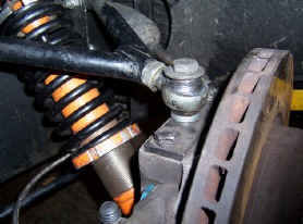
Remove brake caliper from mounting with 2 x 17mm bolts from behind.
It may be necessary to lever the back of the brake pads slightly to allow enough room to slide the caliper off the disk.
Support the caliper, so there is no strain on the brake hose.
Remove the disk
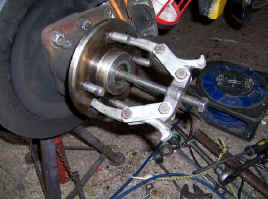
Use a bearing puller to push the drive shaft out of the rear bearings and remove the hub
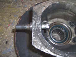
The bearings are now open to dirt, so clean around the area with a clean cloth.
Undo the 3 bolts holding the upright onto the wishbones. Note the position of the various spacers for reassembly.
Remove the upright and bearing hub
Split the bearing hub from the aluminium upright with the 4 hex head bolts. Remove the disk backing plate. Store the bearing hub in a clean plastic bag to keep the dirt out.
Machining the Upright
Mark a line 6mm down along the top back of the upright You can either take this to a local machine shop and have a milling machine used, or I did it quite successfully using a rotary file to remove the majority of the material, and finished with a hand file. The cut slot is wide enough to prevent any possible rose joint contact.
Reassembly Notes
If you are reusing the nylock nuts, clean the threads, and apply locktight thread compound to ensure nothing comes loose. New nuts are preferable. The hub will need knocking back on to the drive shaft with a rubber mallet before its pulled fully home with the 40mm nut. The nut needs to be done to 200flb torque – bloody tight.
The front bush on the lower wishbone is a rubber, and should not be tightened until the full car load is on the suspension.
I'd recommend a couple of thick washers are placed under the top rose joint nut, to take up the extra 6mm of thread. You don’t want to reach the end of the thread before the joint is tight.
Anti-Roll Bars
A few G33’s had front anti-roll bars fitted, and it was also available as a factory supplied extra. Ginetta had tried various roll bar thicknesses on the race track (under advice from Mark Hales), finally ending up with an 18mm diameter one. Fitting one can be a mixed blessing as for smooth track use body roll is undesirable, and an anti-roll bar helps prevent this by linking the front lower wishbones together through a pivoting bar and the thickness of this bar will control how much give there is between the wishbones. As the car starts to roll and the inside wishbone lifts, some of this movement is transferred to the outer wishbone to counteract the body roll. This can sharpen the turn in slightly, but reduces the general compliancy of the suspension. To some extent anti-roll bars are fitted to overcome other areas of deficiency in the suspension design. Reducing body roll on the G33 does help mask the problem of the differing front and rear roll centres. As said before it's all a compromise to identify how you want to use the car, and what suit's one person may not suit another.
Choice of Tyres
The original wheel fitment was going to be a 195 x50 x 15", but when this looked over small in the wheel aches, Ginetta increased the size to 215 x 50 x 15. Such large tyres on such a light vehicle, can cause the tyres to steer the car over rougher roads, not the other way around! You can reduce the tyre width to 205 x 50 (or 55) x 15 to sharpen the steering without significant loss of grip. When choosing tyres, the grip of a tyre is stated as its traction rating on the side wall. This goes from "A" downwards through B and C, but this rating is only a test of the tyres ability to grip when locked on concrete. Not really a dry cornering test. Just about every half decent tyre you come across will be a "A" rating unless it's really bad, and the odd one may be rated as "AA" that is the best you can get for this test. it's much better indication of grip is the tyre's wear rating and this is also stamped on the sidewall. By their nature soft tyres wear faster, but also grip better. Typical examples are 100 - 200 really soft high grip, 200 - 300, sporting but good wear and 300 + for lower grip and long life. A G33 is best suited around or less than 200 for grip and wear as the car is light weight. Problem with grip ratings however is they don't seem consistent between manufacturers. I personally like the Goodyear F1.
From one of our racers:
“I have tried Yoko A520's, Avon CR28 Sports and Yoko A032Rs (soft compound). The A520s were dreadful, even for a List 1A tyre! CR28 Sports (List 1B) would fair better than A032Rs (also List 1B) on the road, but you'll still not get many miles out of them. But do you do a lot of miles in your G33? If less than say 1000 miles a year then the Avons would get my vote. They are also better in the wet than A032Rs when the A032Rs get to the half-worn stage. One of the guys in the GOC Speed Championship has A048Rs on his G33 and doesn't rate them. He prefers the Avons. I think ACB10's would melt the first time you went on a 50 mile trip on a hot day! (Same with A032Rs in super-soft compound).”
Spring Rates
As already mentioned, the springing rates used on the factory cars were pretty hard, used to help cover up some basic deficiencies in the suspension geometry. Standard spring rates seem to vary from 300lb to 325lb in various combinations front and rear. Personally I run 275lb on the front and 300lb on the rear and am happy with the road handling without being bone jarringly hard and bouncing across the road instead of following it.
All the above results I have found are from my personal experience on setting the car up. If you have any comments or further information on this subject please feel free to drop me an email. Also thanks to Dave Gallager and Duncan Campbell for their input.